PCB routing is the core process of connecting electronic components on a circuit board, determining the efficiency and accuracy of signal transmission between components. Routing acts as the “highway” for these signals, carrying information flow and ensuring seamless communication between components. Good PCB routing not only maintains signal integrity but also prevents interference and signal interruptions, thereby ensuring the stability and reliability of the entire system.
1. Optimizing Signal Paths: The routing on a PCB serves as the conduit for electrical signals, ensuring that voltage or current can efficiently propagate between different parts of the circuit. Signal path design must consider the shortest distance, minimal vias, and appropriate width to avoid impedance mismatch and signal reflection.
2. Design of Power and Ground Layers: Power and ground layers are crucial in PCB design. Keeping power and ground layers symmetrical and centered helps reduce electromagnetic interference (EMI) and maintain mechanical stability. Additionally, providing dedicated routing layers for critical signals can reduce loop areas and ensure signal quality.
3. Differential Pair Routing and Clock Signal Handling: High-speed differential pair signals require equal lengths of traces to maintain impedance balance and minimize skew. For clock signals and other critical signals, controlled impedance routing and proper length matching are essential to prevent timing uncertainties and signal misalignment.
Manual Routing: Requires designers to draw routes manually, allowing precise control over the position and length of each trace. While this method can optimize signal paths for critical routes and reduce interference, it is time-consuming and less efficient for complex designs.
Automated Routing: Relies on algorithms within PCB design software to quickly generate connection paths, enhancing design efficiency and consistency, suitable for simple designs or basic connections. However, automated routing can lead to longer traces, signal integrity issues, and suboptimal component layout, particularly in high-density designs.
Although automated routing tools increase efficiency, manual routing remains indispensable for complex designs, especially in high-frequency circuits or multilayer boards. Designers often use a combination of automated and manual routing to ensure signal integrity and system stability in critical parts of the circuit.
1. Enhancing Circuit Performance and Stability: Well-designed routing ensures efficient signal transmission between components, reducing delays and distortion, thereby improving overall speed and responsiveness of the circuit.
2. Optimizing Signal Integrity: Proper routing maintains the quality of electrical signals, preventing distortion and ensuring accurate information transmission, which is crucial in high-speed circuits.
3. Reducing Interference and Crosstalk: Effective routing minimizes the risk of electromagnetic interference and crosstalk by properly spacing traces and avoiding sensitive components, protecting signal quality and preventing unwanted signal coupling.
4. Maintaining Reliability: Thoughtful routing reduces signal reflection, noise, and power distribution issues, ensuring stable power delivery to components and preventing performance instability or premature component failure.
1. Signal Distortion and Delay: Poor routing can lead to impedance mismatch, signal reflection, or excessively long traces, resulting in signal waveform changes and timing issues that impact component communication and circuit performance.
2. Interference and Noise: Incorrect routing may expose traces to interference from adjacent components or external sources, introducing noise and reducing signal quality, leading to data transmission errors.
3. Reduced Reliability: Poorly routed circuits are more prone to failure, potentially encountering unexpected voltage drops, thermal issues, or damaged connections, leading to equipment malfunctions or performance degradation.
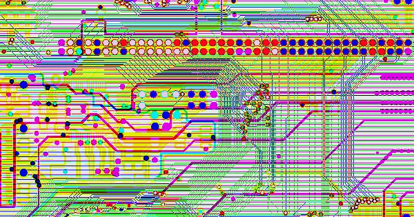
Different signal types need prioritized handling during PCB design. Critical signals such as analog small signals, high-speed signals, and clock signals should be routed first. These signals are sensitive to noise and interference, requiring special routing layers and minimal loop areas. Manual routing, shielding, and maintaining safe spacing are effective measures to ensure signal quality.
Ground traces should be wider than power traces, which in turn should be wider than signal traces. For a 1-ounce copper board, a 1mm trace width typically carries 1A current. Ground traces should be densely routed and aligned parallel to signal traces to minimize interference and noise, ensuring signal integrity.
In PCB design, it is crucial to avoid mixing signal traces with power traces. Signal traces should be kept away from power traces to prevent interference from power noise. Especially for high-frequency signals, routing should be short and direct to reduce transmission delays and losses. Ground and power traces should be separated to avoid mutual interference, particularly in high-power and high-frequency circuits.
Routing around oscillators (crystals) should avoid blank areas, especially beneath the oscillator, and stay away from power sections. This prevents interference between power and clock signals that could distort clock signals and affect overall circuit stability. Similarly, routing for sensitive signals (such as analog signals) should be separated from digital signals. Isolation of analog and digital grounds can be achieved using ferrite beads or zero-ohm resistors to prevent signal interference.
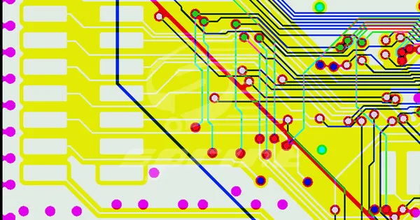
Sharp angles and right-angle traces in high-speed signal routing can cause impedance discontinuities. Right-angle corners can act as capacitive loads on traces, slowing down signal rise times, especially in high-speed and high-frequency applications. Angles should be avoided, or if necessary, use 135° angles for bends.
Differential pairs, used for data transmission, require equal lengths of traces and similar routing paths close together to reduce common-mode interference. Differential pairs should be routed separately from single-ended signals to avoid crossing or overlapping, which can introduce interference.
The area of the loop formed by signal traces and their return paths should be minimized. Smaller loop areas reduce the potential for external radiation and interference from external sources. Ensure signal grounds are not split, and use vias where necessary to keep the ground loop as small as possible.
Snake traces are used to adjust delays to meet timing requirements but can degrade signal quality and alter transmission delays. If snake routing is required, maintain a minimum bend radius and ensure trace spacing is four times the trace width to reduce crosstalk. Impedance matching is crucial in high-speed circuits to minimize signal reflection and interference, ensuring signal integrity.
Good power line design is vital for reducing signal interference and electromagnetic interference. Power lines should be wide and short to reduce resistance and inductance, ensuring stable power supply. Ground lines should be close to signal lines and form loops to provide good return paths, minimizing signal loop areas.
After completing PCB routing design, simulation analysis and prototype verification are essential steps. Simulation helps assess the performance and stability of the routing design, identify potential interference issues, and make timely adjustments. This greatly reduces design errors and improves circuit reliability.
PCB routing is both an art and a technical discipline. Thoughtful routing ensures optimal circuit performance, signal integrity, and long-term system stability. At SprintPCB, a leading PCB factory, we understand that achieving the best results requires not only advanced technology but also expertise in both design and manufacturing processes. Designers must consider electrical characteristics, mechanical structure, and manufacturing techniques to ensure efficient and reliable circuit design. As a premier PCB manufacturer, SprintPCB is committed to delivering high-quality solutions that meet the highest standards of performance and reliability.

Customer support