FPC (Flexible Printed Circuit Board) is a type of highly reliable and flexible printed circuit board made from polyimide or polyester thin films. It is characterized by high wiring density, light weight, thinness, and excellent bending flexibility.
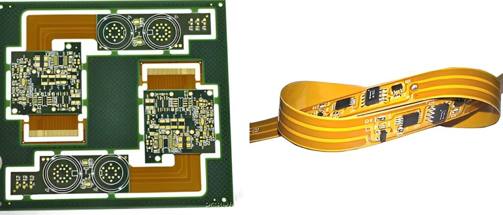
Before we unveil the mystery of FPC manufacturing, we need to know that the materials constituting a flexible printed circuit (FPC) are insulating film, conductor, and adhesive.
Insulating film forms the base layer of the circuit, and adhesive bonds the copper foil to the insulating layer. In multi-layer designs, it is bonded together with inner layers. They are also used as protective coverings to isolate the circuit from dust and moisture, and to reduce stress during flexing. The copper foil forms the conductive layer.
In some flexible circuits, rigid components made of aluminum or stainless steel are employed to provide dimensional stability, physical support for components and wires, and stress relief. Adhesives are used to bond the rigid components with the flexible circuit. Additionally, another material sometimes applied in flexible circuits is the adhesive layer film, which is coated with adhesive on both sides of an insulating thin film.
The adhesive layer film provides environmental protection, electronic insulation functionality, eliminates the need for an additional layer of film, and enables the creation of multi-layer circuits with fewer adhesive layers.
Insulating film materials come in many types, but the most used ones are polyimide and polyester materials. In the United States, 80% of all flexible circuit manufacturers use polyimide film materials, while approximately 20% utilize polyester film materials.
Polyimide materials are non-flammable, dimensionally stable, have high tensile strength, and can withstand soldering temperatures. Polyester, also known as polyethylene terephthalate (PET), has similar physical properties to polyimide, including low dielectric constant and minimal moisture absorption.
However, it is not suitable for high-temperature applications as its melting point is 250°C and its glass transition temperature (Tg) is 80°C. These limitations restrict their use in applications that require extensive end-to-end soldering.
In low-temperature applications, they exhibit rigidity. Nevertheless, they are still suitable for use in products such as telephones and other items that do not need to be exposed to harsh environments.
Polyimide insulation films are typically combined with polyimide or acrylic adhesives, while polyester insulation materials are combined with polyester adhesives. The advantages of combining these materials with similar properties include dimensional stability after soldering or multiple lamination cycles.
Other important characteristics of the adhesives include low dielectric constant, high insulation resistance, high glass transition temperature, and low moisture absorption rate.
Copper foil is suitable as a conductor for use in flexible circuits. It can be produced through electroplating or electro-deposition (ED).
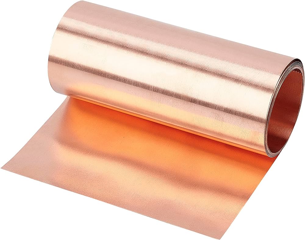
The side of the copper foil produced through electro-deposition has a glossy surface, while the other side has a dull appearance due to processing. It is a flexible material that can be manufactured in various thicknesses and widths. The dull side of ED copper foil is often subjected to special treatments to improve its adhesive properties.
In addition to its flexibility, forged copper foil also possesses the characteristics of being hard and smooth, making it suitable for applications that require dynamic flexing.
Adhesive, in addition to bonding insulating films to conductive materials, can also be used as a coating layer for protective and covering purposes. The main difference between the two lies in the application method used.
The adhesive coating over the insulating film is intended to form a stacked circuit structure. The screening printing technique is used for the adhesive's coating application. Not all stacked structures contain adhesive, and those without adhesive form thinner circuits with greater flexibility. In comparison to adhesive-based stacked structures, it exhibits better thermal conductivity.
Due to the thin and flexible nature of adhesive-free flexible circuits and the elimination of adhesive thermal resistance, it can be used in working environments where adhesive-based stacked structures cannot be employed.
Next, please follow our footsteps and get ready to decrypt the manufacturing process of FPC (Flexible Printed Circuit) boards.
FPC (flexible circuit board) manufacturing process
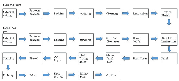
Material Cutting
To minimize waste, every production process of FPC includes initial cutting of the base material. Precise cutting during material processing helps avoid waste caused by excess material.
Chemical Cleaning
This step is primarily aimed at removing the oxide layer on the conductive base material and copper foil surface. If not cleaned, the oxide layer can lead to continuous oxidation of the FPC during use, resulting in a shortened lifespan. Therefore, cleaning is necessary to ensure the long-term reliability and stability of the circuit board and reduce losses caused by oxidation.
Inner Layer Anti-Corrosion Dry Film (FPC)
First, the circuit pattern is created on the film. Then, the film with the anti-corrosion dry film (photosensitive film) is aligned with the base material, and an exposure machine is used to expose the circuit pattern from the film onto the base material. This transfers the circuit pattern onto the copper foil.
Acid Etching (FPC Etching)
In the production of FPC soft boards, acid solutions such as hydrochloric acid or sulfuric acid are commonly used for chemical etching. However, alkaline solutions like ammonia water are often used for etching hard circuitry as they exhibit acid characteristics more easily.
Chemical Cleaning
This step aims to prevent any remaining solution from etching process from being trapped in the circuit and remove any impurities on the surface of the FPC through plasma cleaning.
Inner Layer Cover Film Alignment
Prior to the aforementioned steps, the cover film for the soft board needs to be shaped accordingly and aligned with the FPC. Then, a soldering iron is used to preliminarily fix the cover film to the pads.
Lamination
During the production process, lamination is typically divided into fast lamination and slow lamination. Fast lamination is commonly used for initial lamination, and the maximum allowable thickness is determined based on standard references. After lamination is completed, the product is inspected to confirm the absence of bubbles or glue overflow.
Baking
This step involves high-temperature treatment to facilitate the flow and leveling of the adhesive between the circuit board and cover film, ensuring a more complete bond. The adhesive melts and fills the gaps between the copper foil and cover film, tightly bonding them together after high-temperature baking.
Character Printing on FPC Circuit Board
The process of manufacturing a FPC (flexible circuit board) also includes transferring characters from the film onto the mesh screen and using the screen to print characters onto the FPC. This process also involves inspecting the printing results to ensure there are no missing or insufficiently printed characters.
The surface treatment of FPC (Flexible Printed Circuit Board) serves the fundamental purpose of ensuring good solderability or electrical performance. Since copper in the natural environment tends to exist in the form of oxides in the air, it is unlikely to remain in its original copper state for a long time, so it needs to undergo other treatments. The common surface treatment processes for FPC are as follows:
Hot Air Leveling (HASL)
Hot Air Leveling, also known as hot air solder leveling (commonly known as HASL), is a process in which molten solder (lead) is coated on the surface of the PCB and then heated and compressed with hot air to create a coating layer that is both resistant to copper oxidation and provides good solderability.
During hot air leveling, a copper-tin intermetallic compound is formed at the junction of the solder and copper. The PCB is immersed in molten solder during hot air leveling; the air knife blows the liquid solder flat before it solidifies; the air knife minimizes the crescent-shaped solder on the copper surface and prevents solder bridging.
Organic Solderability Preservatives (OSP)
OSP is a process for surface treatment of FPC that complies with RoHS directive requirements. Simply put, OSP is a chemical method of growing an organic film on the clean bare copper surface. This film has anti-oxidation, heat resistance, and moisture resistance properties to protect the copper surface from further rusting (oxidation or sulfidation) in normal environmental conditions.
However, in subsequent high-temperature soldering processes, this protective film must be easily and quickly removed by flux so that the exposed clean copper surface can immediately form a strong solder joint.
Full-Board Electroless Nickel Gold (ENIG)
Full-board ENIG involves depositing a layer of nickel followed by a layer of gold on the surface conductor of the PCB. The main purpose of nickel plating is to prevent diffusion between gold and copper. There are two types of current ENIG processes: soft gold (pure gold, with a non-bright appearance) and hard gold (smooth and hard surface, wear-resistant, containing cobalt and other elements, with a bright appearance).
Soft gold is mainly used for wire bonding in chip packaging, while hard gold is mainly used for non-soldered electrical interconnections.
Immersion Gold (ENIG)
Immersion gold involves coating the copper surface with a thick layer of electro-conductive nickel-gold alloy, which provides long-term protection for the PCB. Additionally, immersion gold has better tolerance to environmental conditions compared to other surface treatment processes. Furthermore, immersion gold can prevent copper dissolution, which is beneficial for lead-free assembly.
Immersion Tin (ENIG)
Since all current solders are tin based, a thin layer can match any type of solder. Immersion tin forms a flat copper-tin intermetallic compound, which gives it excellent solderability like hot air leveling without the flatness issues associated with hot air leveling. Immersion tin-plated boards should not be stored for too long and must be assembled in the order of tin immersion.
Immersion Silver (ENIG)
Immersion silver is a process that falls between organic coating and chemical nickel/gold plating. The process is simple and fast. Even when exposed to hot, humid, and polluted environments, silver can still maintain good solderability but may lose its luster. Immersion silver does not have the same level of physical strength as chemical nickel/gold plating because there is no nickel layer beneath the silver.
Chemical Nickel Palladium Gold (ENIG)
Chemical nickel palladium gold, compared to immersion gold, adds a layer of palladium between nickel and gold. Palladium can prevent corrosion caused by displacement reactions and prepare for gold plating. Gold tightly covers the palladium, providing good contact surface.
Hard Gold Electroplating
Hard gold electroplating is used to improve the wear resistance and increase the number of insertions and withdrawals of products.
Final Inspection
This is the last crucial step in the flexible printed circuit (FPC) manufacturing process, where all FPC boards must undergo production floor inspection to ensure quality and performance assurance. Currently, domestic FPC quality inspection heavily relies on manual visual inspection, which is costly and inefficient. However, for testing and validating FPC performance, we can employ the following methods.
Electrical Testing(FPC)
Electrical Continuity Test: Used to verify whether the wires and connection points in the Flexible Printed Circuit (FPC) are correctly connected. This test typically employs methods such as continuity testing or bed-of-nails testing to check the circuit's connectivity.
Resistance Test: Used to measure the resistance value of the circuit paths in the FPC. This test ensures that the resistance of the wires falls within the specified range to guarantee stable signal transmission.
Insulation Test: Used to detect the insulation between the wires in the FPC and between the wires and the substrate. This test ensures that the FPC does not experience circuit short-circuits or leakage issues under high voltage conditions.
Reliability Testing(FPC)
Bend Life Testing: By repeatedly bending the FPC, it simulates the bending conditions in actual applications. This test can assess the bending performance and durability of the FPC during long-term use.
Thermal Cycling Testing: The FPC undergoes cyclic changes between high and low temperature environments to simulate the impact of temperature variations on the FPC. This test can evaluate the reliability and stability of the FPC under temperature change conditions.
Humidity Cycling Testing: The FPC undergoes cyclic changes between high temperature and high humidity, as well as low temperature and low humidity environments, to simulate the effects of humidity and temperature on the FPC. This test can assess the durability and reliability of the FPC in humid environments.
Environmental Testing(FPC)
Corrosion Resistance Testing: Expose the FPC to different corrosive media to evaluate its resistance to chemical corrosion. This test ensures the stability and reliability of the FPC in specific environments.
High Temperature Testing: Place the FPC in a high-temperature environment to test its performance and stability under high-temperature conditions. This test assesses the FPC's tolerance in high-temperature environments.
Low Temperature Testing: Place the FPC in a low-temperature environment to test its performance and stability under low-temperature conditions. This test evaluates the FPC's tolerance in low-temperature environments.
These testing methods and tools can assist manufacturers in evaluating and validating the performance, reliability, and stability of FPC (Flexible Printed Circuit) to ensure its proper functioning and long-term durability in real-world applications. When conducting tests, it is recommended to choose appropriate testing methods and tools based on the specific requirements and application environment of the FPC and adhere to relevant testing standards and specifications.
In summary, FPC (Flexible Printed Circuit Board) manufacturing is a complex and crucial process that requires attention to multiple aspects.
By understanding the basic principles, selecting appropriate materials and processes, considering design factors, implementing strict quality control, and testing and verifying FPC performance, we can ensure the production of high-quality, reliable, and stable FPC products. Through continuous improvement and innovation, we can constantly enhance the efficiency and quality of FPC manufacturing, meet market demands, and maintain a competitive advantage.
It is hoped that this article can help readers gain a better understanding of the important considerations in FPC manufacturing and inspire them to further explore and apply FPC technology. If needed, readers can conduct further research and refer to resources and materials in related fields to deepen their understanding and practical experience in
FPC manufacturing.