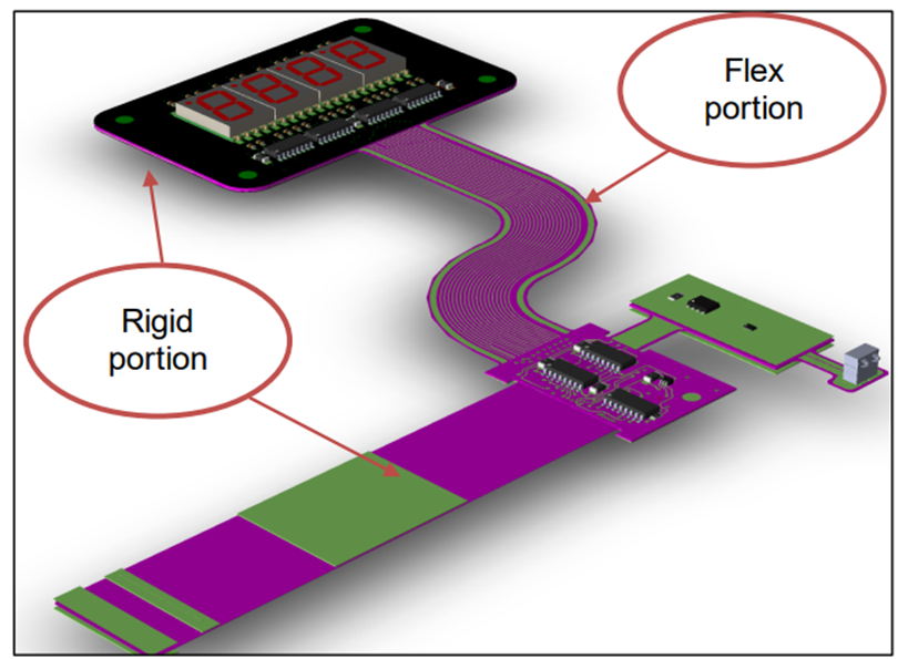
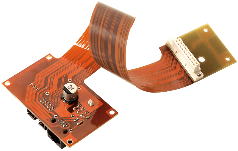
Rigid-Flex boards are innovative circuit board designs that possess both rigidity and flexibility. This article will introduce the manufacturing steps and key points of Rigid-Flex boards to help readers understand how to produce these flexible circuit boards.
Producing Rigid-Flex boards involves several steps and specialized manufacturing techniques. The first step in producing Rigid-Flex boards is design and planning. This involves determining the locations of rigid and flexible areas on the board, positioning of traces and connectors, planning signal and power layers, and so on. Professional circuit design software such as Altium Designer or Cadence Allegro is used for designing and ensuring compliance with circuit design requirements and specifications.
The next step is the selection of the substrate material. The combination of rigid-flex boards is achieved by bonding a flexible board (FCCL) and a rigid board (FR4) together using an adhesive.
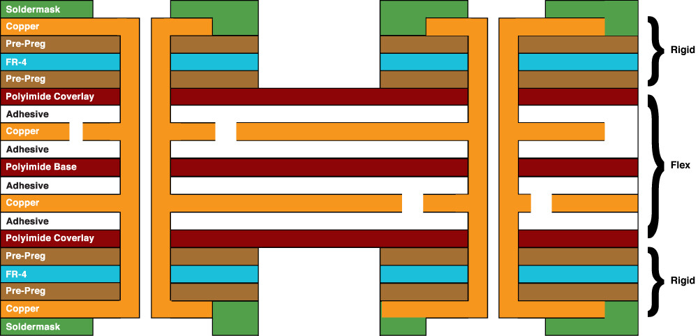
1. The flexible board section is composed of two parts: the flexible board substrate and the cover film. The flexible board substrate can be further divided into two types: adhesive-based and non-adhesive-based. The adhesive-based substrate is composed of adhesive, copper foil, and PI (polyimide). It has poor reliability and flexural properties. The non-adhesive-based substrate is composed of PI (polyimide) and copper foil. It has good reliability and flexural properties. The cover film is composed of PI and bonding agents. The bonding agents include acrylic adhesive and epoxy resin adhesive. 2. Adhesive Section: The adhesive section consists of non-flowing semi-cured sheets (No Flow PP, abbreviated as NF) and pure adhesive (acrylic adhesive). NF: Composed of epoxy resin, glass fibers, and fillers, NF has minimal adhesive overflow and is used for selectively bonding products. Pure adhesive: Commonly known as "acrylic adhesive" or scientifically referred to as "acrylic acid." It has good flexibility but a relatively large thermal expansion coefficient, primarily used for laminating multiple layers of flexible boards. 3. For the rigid board section, commonly used materials include FR4, KB, and Shengyi.
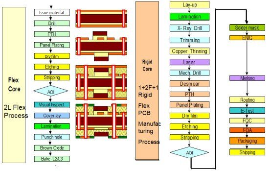
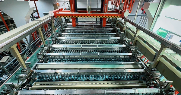
After selecting the materials, we move on to the production phase of rigid-flex boards. The first step is to create a rigid portion of the board. This involves processes such as drilling holes, through-hole plating, copper plating, etching, and solder mask application, like standard PCB manufacturing. According to the design requirements, drilling operations are performed on a rigid board. These holes are used for component installation, establishing interconnections, and providing electrical pathways. Drilling can be done using a drilling machine or a laser drilling machine. After drilling, a thin layer of copper is plated on the inner walls of the holes through through-hole electroplating. This is done to ensure that the inner walls of the holes are conductive for future electrical connections. A layer of copper is coated on the entire surface of the rigid board to form a conductive layer. This copper layer serves as the foundation of the circuit, connecting various components and interconnect paths. Through an etching process, the non-circuit portions covered by the copper layer are removed, leaving only the required wires and traces for the circuit. This creates the circuit pattern. After etching, a solder mask is applied as a protective layer over the copper layer to prevent unwanted solder connections. After completing the above steps, the fabrication of the rigid part of the circuit is essentially finished. Next, the selected flexible material will be laminated onto a release film or substrate to prepare the flexible substrate. A technique like PCB manufacturing will be used, involving the application of a copper layer and patterning processes. The rigid and flexible layers will be precisely aligned and bonded together. This step may require the use of adhesives, heat, and pressure to form a strong bond between the layers. Create vias to establish electrical connections between rigid and flexible layers. This can be achieved through processes such as laser drilling or mechanical drilling of microvias, depending on the design requirements. Install components onto the rigid portion of the board using either standard surface mount technology (SMT) or through-hole technology. When placing components near the bending area, special attention should be paid to ensure that they can withstand the bending. Once the components are installed, the flexible portion of the board can be bent and formed according to the desired shape. This is typically achieved by using dedicated equipment that applies controlled pressure and heat to create the desired bending points.
Finally, thorough testing and inspection are conducted to ensure the functionality and reliability of the rigid-flex boards. This includes thermal stress testing, thermal shock testing, humidity and insulation resistance testing, voltage endurance testing, peel strength testing, tensile testing, and flexure testing.Thermal Stress Test Test Purpose: To assess the impact of thermal stress on the bonding quality and coating integrity of the finished rigid-flex board after baking and high-temperature shock. Testing Equipment: Oven, solder pot Testing Method: Place the rigid-flex board in the oven for baking according to customer specifications. If there are no specific instructions, follow IPC standards and bake at 120°C for a minimum of 2 hours. Use tongs to remove the test board from the oven and place it on a rack to cool down to room temperature. Apply Flux to both sides of the test board, clamp it with tongs, and subject it to thermal stress testing by immersing it in molten solder on the surface of the solder pot. The thermal stress temperature should be maintained at 288±5°C for a duration of 10+1/-0 seconds, repeated 3 times (or as specified by the customer). Acceptance Criteria: The presence of delamination or blistering is not allowed, as per IPC-TM-650268. Hot and Cold Shock Testing Testing Purpose: To assess the quality of the coating and material structure of rigid-flex boards under high and low-temperature cyclic shocks. Testing Instruments: A) Thermal Shock Chamber B) Micro-ohmmeter C) Metallographic Microscope Testing Method: Identify the conductive circuits to be tested on the test board and measure their resistance using a micro-ohmmeter. Place the test board in the thermal shock chamber and subject it to the specified conditions, either according to customer requirements or IPC standards, at a temperature range of -55°C to 125°C for 15 minutes, with 100 cycles. After testing, allow the board to return to room temperature and measure the conductivity resistance using a micro-ohmmeter. Acceptance Criteria: According to IPC-TM-6502672, the percentage increase in resistance of the tested board after the test should not exceed 10% ((after test - before test) / before test * 100); there should be no delamination or cracking observed in the cross-sectional analysis. Moisture and Insulation Resistance Testing Test Purpose: To assess the influence of high temperature and humidity on the insulation resistance of the finished rigid-flex board. Test Equipment: A) Constant temperature oven B) Megohmmeter Test Method: Place the test specimen board into the oven and bake it at (50±5°C, 3 hours), then remove and allow it to cool to room temperature. Place the test rigid-flex board into the constant temperature and humidity chamber and apply a voltage of 100±10VDC. Measure the insulation resistance of the test board using a megohmmeter (measurement voltage: 500VDC). Set the temperature and humidity and start the constant temperature and humidity machine (conditions based on customer or IPC specifications: temperature: 50±5°C, humidity: 85~93%RH, duration: 7 days). After the test is completed, place the test rigid-flex board at room temperature and measure its insulation resistance within 1-2 hours, recording the measured value. Acceptance Criteria: According to IPC-TM-650263IPC-6012-294&2.10.1, the insulation resistance should be ≥500MΩ before the test and ≥100MΩ after the test. Voltage Withstanding Test Test Purpose: To determine the minimum voltage at which the insulation between rigid-flex board traces is penetrated. Testing Equipment: High-voltage testing machine Testing Method: Place the rigid-flex board in an oven and bake it at a temperature of 49-60°C for a minimum of 3 hours. Remove the board and let it cool to room temperature. Open the voltage withstand tester and follow customer requirements or IPC testing conditions (test voltage: 500+15/-0VDC, test duration: 30+3/-0 seconds, leakage current: 0.5mA). Criteria for Judgement: According to IPC-TM-650257, after a 30-second test, a green light indicates a pass (OK), while a red light indicates a failure (NG). Peel-off Test Test Purpose: To test the strength of S/M, ink, and coating adhesion on the copper surface for qualification. Testing Equipment: 3M Tape (Model 600, width 0.5 inch) Testing Method: Cut approximately 2 inches of 3M tape and stick it onto the board. Then, use gloves to press the tape tightly, removing any air bubbles. Quickly pull the tape horizontally in the direction parallel to the test rigid-flex board (the tape should be pressed and pulled within 1 minute). Acceptance Criteria: According to IPC-TM-65024.281&241, visually inspect the tape being peeled off. No residues of S/M, ink, or coating should remain on the tape. Pull Test Test Purpose: To test the adhesion between PP and copper foil. Test Equipment: Pull testing machine. Test Method: Measure the width of the line to be pulled and select a line that is at least 1" away from the board edge and has a width of at least 0.125". Use a heat gun to blow the front end of the line to be tested and scrape the line with a scraper for approximately 0.5" in length. Fix the scraped end of the line and perform a pull test (at an angle of 90±5 degrees) at a speed of at least 2 inches per minute until a length of at least 1" is reached. Criteria for Judgment: According to IPC-TM-650248&24.81, the finished board specifications should be equal to or greater than 6 lb/inch (1 lb = 0.454 kg). Substrate: A) 1/3 oz > 5 lb/inch, B) 0.5 oz > 6 lb/inch, C) 1 oz > 8 lb/inch, D) 2 oz > 10 lb/inch. Bend Test Test Purpose: To test the dynamic bending performance of FPC (Flexible Printed Circuit) and ensure the stability of electrical and signal transmission during dynamic use. Test Instrument: Bend testing machine Test Method: Weld the wires to both ends of the test sample circuit and secure them to the bend testing machine. Set the bend test parameters according to customer specifications or IPC standards: the inner diameter of the reciprocating bending is 2.0±0.2mm, the reciprocating motion stroke is 120+5mm, and the test speed is 100RPM. The number of bends is counted until the current interruption occurs (the rate of impedance change needs to be measured during the test). Test Standard: Based on IPC-TM-65024.3. Finally, we perform the final finishing on the rigid-flex board, which includes the final surface treatment and protective coating, such as solder mask, surface treatment, and sealing. During the final finishing stage of producing rigid-flex boards, surface treatment and the application of protective coatings are required to provide protection and enhance solderability. Solder Mask: Solder mask is a protective coating applied to a circuit board to cover and protect areas that do not require soldering, such as circuit traces and metal pads. It is typically a green layer of coating, but it can also be in other colors such as red, blue, or white. Solder mask helps prevent short circuits and electrical interference, while providing an additional layer of protection. Surface Finish: Surface finish refers to the application of a coating or plating on the metal surface of a circuit board to enhance its corrosion resistance, solderability, and electrical characteristics. Common methods of surface finish include: Hot Air Solder Leveling (HASL): This is a common surface treatment method that involves coating a layer of molten solder on the metal surface and then removing excess solder using an air knife. Electroless Nickel Immersion Gold (ENIG): This surface treatment method involves sequentially depositing a layer of nickel and a layer of gold on a metal surface. It provides good flatness, solderability, and corrosion resistance, making it suitable for high-precision circuits. Organic Solderability Preservative (OSP): This surface treatment method forms an organic protective layer on the metal surface, providing protection and corrosion resistance. The OSP layer needs to be applied shortly before soldering, as it doesn't possess long-term stability like other surface treatment methods. Conformal Coating: In critical areas of flexible parts and circuit boards, a layer of conformal coating can be applied to provide additional protection. Conformal coating is typically a transparent coating that is applied to the circuit board to cover and protect electronic components, solder joints, and trace lines. This coating helps prevent damage to the circuit board from moisture, dust, chemicals, and other environmental factors, while also providing insulation and corrosion resistance. These final assembly steps contribute to the durability, reliability, and stability of rigid-flex boards. By applying solder mask, surface treatment, and sealing coatings, the lifespan of the circuit boards can be extended, providing additional protection layers to adapt to various environmental conditions. This helps safeguard the boards against moisture, corrosion, short circuits, and other adverse effects while ensuring reliable soldering surfaces for secure connections during the assembly process. The production of rigid-flex boards requires specialized knowledge and techniques, but by following the correct steps and guidelines, high-quality rigid-flex boards can be successfully manufactured. Attention to detail and quality control should be maintained throughout the stages of design, material selection, lamination processing, assembly soldering, and testing validation. With the continuous advancement of technology, rigid-flex boards will play a crucial role in a wider range of electronic devices, offering flexible and reliable solutions for innovative electronic products.

Customer support