Copper is the preferred material for wires and traces in printed circuit boards due to its low resistance, second only to silver. When an ohm meter is placed over a trace, the DC resistance is negligible. However, this is not the case for AC impedance. Impedance is frequency-dependent, and all wires and traces generate some impedance to the current flowing from any driver. Although trace impedance typically becomes a concern only with fast signal rise times, it's crucial to be aware of its existence and potential impact. But why does trace impedance matter? What causes it, and can it be managed? If you've heard the term "controlled impedance," you may already know that it's possible to regulate impedance. However, to comprehend how and why, it's essential to have a basic understanding of trace impedance's nature.
How Trace Impedance Works
Each trace has a distributed series inductance that is almost indistinguishable and inversely proportional to the trace's cross-sectional area. As rise times increase, the resulting impedance becomes more noticeable. Additionally, each trace has capacitance distributed along the trace and the signal return path, which is determined by the trace's width and the dielectric of the material between the signal return path and the trace. Again, if the rise times increase, the resulting impedance generated by the current attempting to flow through this capacitance can be substantial. Your drivers perceive all traces as distributed LC circuits, and the trace AC impedance arises from this distributed LC circuit. This is referred to as uncontrolled impedance since we make no attempt to design the trace environment to account for this impedance and let the inductance and capacitance vary naturally along the trace. Since the resulting impedance typically does not affect operations, there is no need to spend time or money developing methods to regulate it.
Controlled Impedance
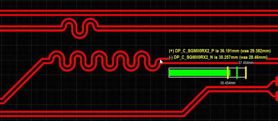
To design a controlled impedance circuit, we need to use specific formulas and software tools to calculate the correct values for each of these three geometric features. The trace width and spacing between the signal return path and the signal trace are typically the easiest to adjust, while the dielectric coefficient is typically fixed by the circuit board material. Once we’ve calculated the necessary values, we can apply them to the circuit design and manufacture the board to meet these specifications. By designing a controlled impedance circuit, we can minimize reflections and ensure that our signals travel smoothly and efficiently along the traces without any degradation or loss of signal quality. In summary, controlling impedance in a circuit requires carefully controlling the geometric features of the traces, including width, spacing, and dielectric coefficient. By doing so, we can create a circuit that maintains a constant impedance along the entire length of the trace, leading to improved signal quality and performance.
How to Determine Pcb Trace Impedance
To ensure controlled impedance in printed circuit boards, it's essential to accurately measure impedance. Trace impedance calculators can be found online or in CAD software, and they take into account several parameters that determine impedance, such as trace width, trace thickness, laminate thickness, dielectric thickness, and copper weight. After calculating these parameters, the trace width can be adjusted to achieve the desired impedance. To test the board's effectiveness, it's recommended to use test coupons manufactured on the same panel and at the same time as the actual board. These test coupon traces should be identical to the board traces to get an accurate test result. To manufacture controlled impedance printed circuit boards, it's important to measure impedance accurately. Test coupons are built on either end of the production panel, allowing testers to measure impedance without damaging the board. Impedance can be measured using a Time Domain Reflectometer (TDR), a network analyzer, or a controlled impedance test system. An engineer with experience using controlled impedance test systems will ensure high-quality results. If you need more information or want to order controlled impedance PCBs for your industry, contact Sprintpcb today.

Customer support